
The Sapugaskanda Power Station is a thermal power station with total installed capacity of 160MW. This power station is located at Heiyanthuduwa within the Biyagama Pradeshiya Sabha of Western Province, Sri Lanka.
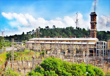
Figure 1: The Power House and Switchyard
Sapugaskanda Power Station consists of two Stations called Station A & Station B. Station A was commissioned in 1984 and houses four V type 20MW PC 4.2 Diesel engines manufactured by SEMT Pielstick. Each engine is coupled with a 25.6MVA generator manufactured by Alsthom Atlantique.
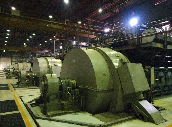
The Station B consists of eight in-line 10MW diesel engines manufactured by MAN B&W. Each engine is coupled with a 12.9MVA generator manufactured by Siemens. Station B comprises two stations called as Station-B1 & Station-B2. The Station B1 was commissioned in 1997 September with four 8L 58/64 engines and Station B2 was commissioned in 1999 October with another four 8L 58/64 engines.
 |
 |
|---|---|
Figure 2: Station B Engines |
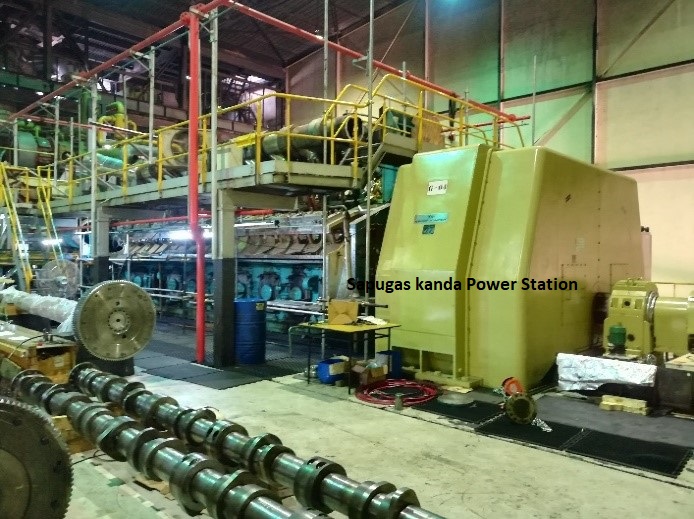
Figure 3: Station A Engine Undergoing 24,000 Running Hour Routine Maintenance |
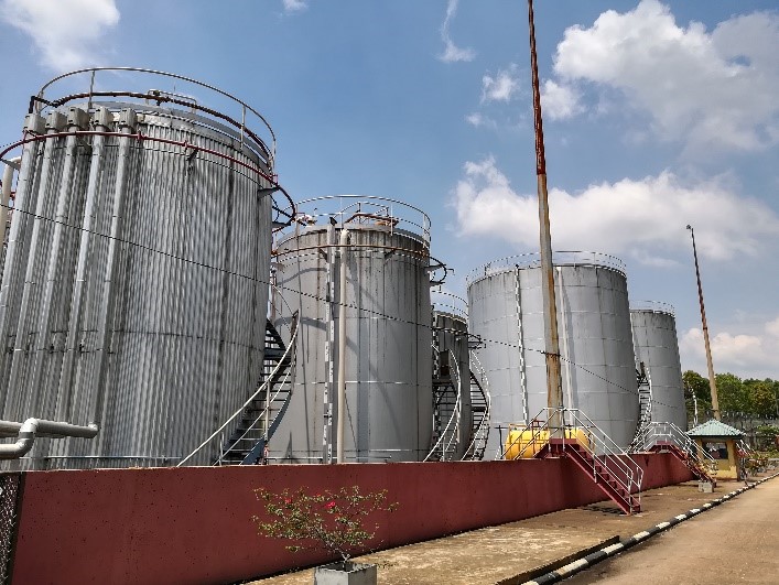
The engines in both stations use diesel (DFO) and heavy fuel oil (HFO) as the fuel. Diesel is used only for startup and shut down processes. Exhaust gas of engines is used to produce hot water which is utilized to increase the temperature of HFO so that correct fuel viscosity is maintained.The cleaning/separation of fuel and lubricating oil is done in Alfa Laval centrifuges. Fuel is delivered to the plant from the Sapugaskanda Oil Refinery located nearby. The delivered fuel is stored in tank farms of both stations.
 |
 |
|---|---|
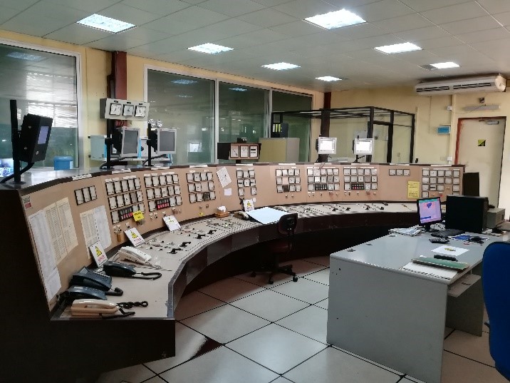
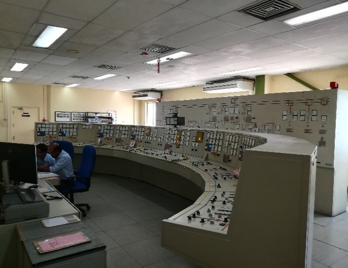
Figure 4: Station A Control Room |
Figure 5: Station B Control Room |
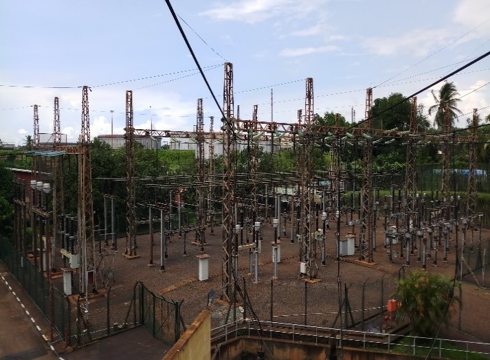
Both Stations generate electricity at 11,000V and step-up to 132kV via five step-up transformers. The Electricity generated is transmitted to Biyagama Receiving Station via two 132kV overhead transmission lines which are designated as Biyagama Line 1 & 2 (thereby fed to the National Power Grid). During plant shutdown, the 400V auxiliary supply is maintained either from these lines or the black start generator.
 |
 |
|---|
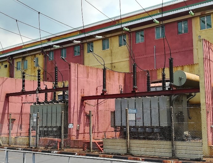
Figure 6: Station B Step Up Transformers & Switchyard
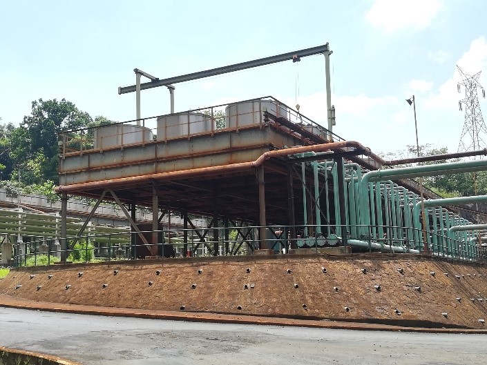
There are several auxiliary systems attached to the engine in both Station A & B. They are fuel system, lubrication oil system, cooling water system (equipped with a cooling tower in Station A and a radiator bank in Station B), hot water system, control air system, starting air system, sludge system, fire detection & control system, data logger & monitoring system and electrical system etc.
 |
 |
|---|---|
Figure 7: Station A Tank Farm |
Figure 8: Station B Radiator Bank |
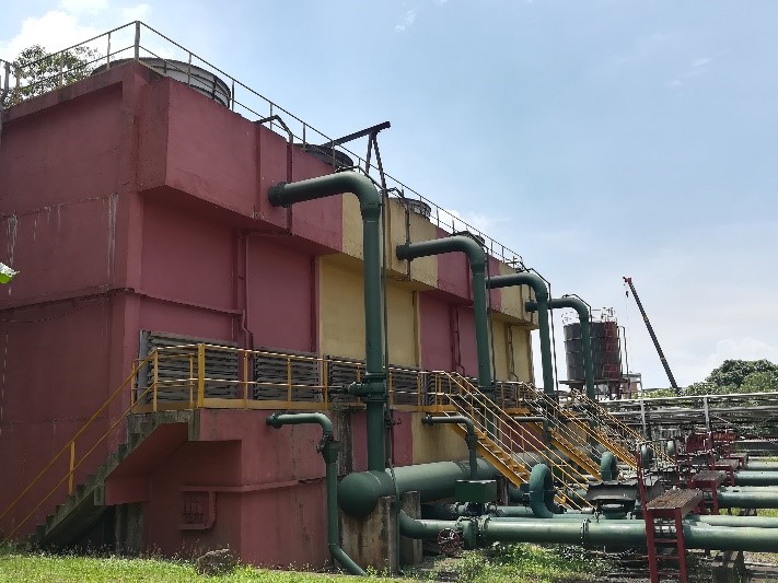
Figure 9: Station A Cooling Tower